3.5 Layout-Versus-Schematic using Netgen
Table of contents
Prerequisites
- It is assumed that you have finished the lessons on creating the schematic with Xschem and the layout of the buffer with magic.
Introduction to Layout-Versus-Schematic (LVS) check
LVS is a process to check if your layout and your original schematic are similar. We need to do this check because when transforming from schematic to layout, you might make different mistakes, for example, a short circuit. The connection and the terminal in the layout are different from the schematic. LVS is an important step in analog design flow to ensure that your layout is identical to your schematic.
In this lesson, we will use Netgen to check if our schematic and the layout are identical. The inputs to LVS are a netlist from the schematic and a netlist extracted from the layout. The layout tool such as magic supports extracting the netlist for LVS. Netgen will compare these two files to decide if the two netlists are identical. If it is not identical, we have to identify the differences and change the layout and/or the netlist so that they are identical. The identical layout and schematic also ensures somewhat that the circuit will work as expected.
Prepare the design for LVS
To do LVS, we will need a netlist from the schematic tools such as xschem and a netlist from the layout tool such as magic. Therefore, we have to use xschem and magic to generate the netlist ready for LVS.
1. Create the netgen folder
First, we change the directory to the folder that we already have the netlist and create a new directory to run the LVS.
mkdir -p $HOME/unic-cass/inverter/netgen
cd $HOME/unic-cass/inverter
(base) cass@unic-cass:~$ mkdir -p $HOME/unic-cass/inverter/netgen
(base) cass@unic-cass:~$ cd $HOME/unic-cass/inverter
(base) cass@unic-cass:~/unic-cass/inverter$
2. Open the schematic in Xschem
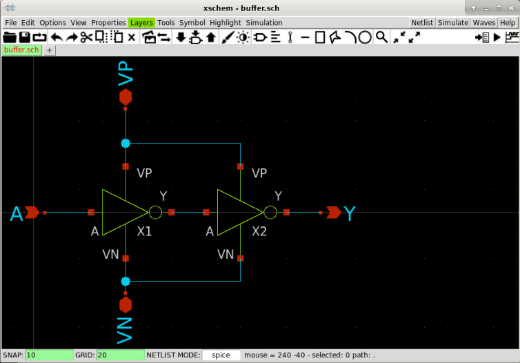
Next we have to open the schematic and export the netlist. If your setup is correct, xschem will open the schematic of the buffer that we designed.
xschem buffer.sch
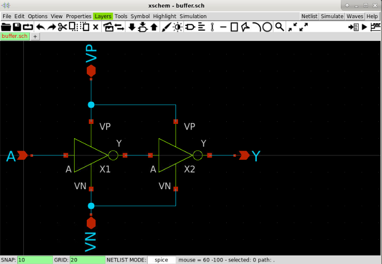
3. Set up the netlist directory
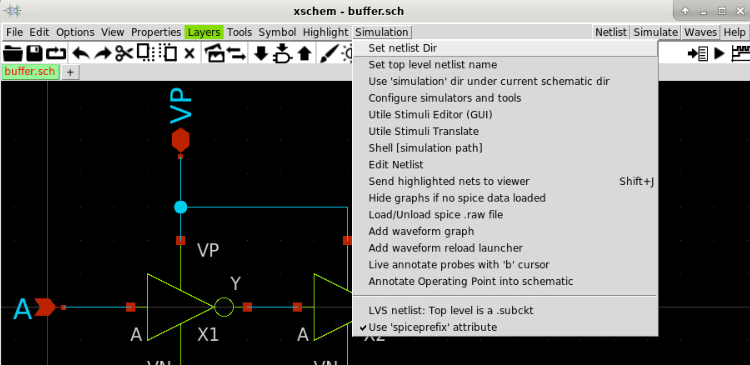
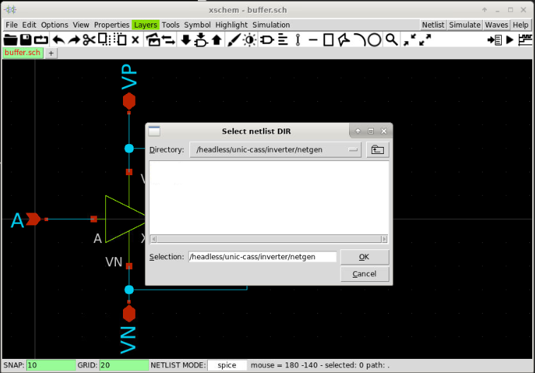
Next, we need to set up the folder for the netlist by selecting Simulation >> Set netlist Dir. Then, we select the netgen directory that we’ve just created and press OK.
4. Generate the schematic netlist
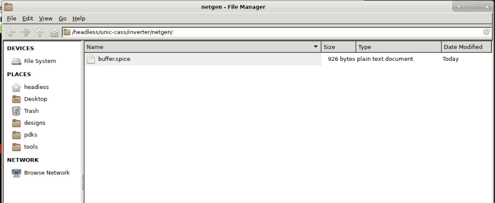
After setting up the netlist directory, we can press the Netlist button to generate the netlist. A new file named buffer.spice should be created in the netgen directory.
5. View the schematic netlist
We can view the netlist by selecting Simulation >> Edit Netlist. An editor window will appear with our netlist. Do not close this window, we can use it to compare the xschem netlist with the magic netlist.
Spice netlist
** sch_path: /home/cass/unic-cass/inverter/buffer.sch
.subckt buffer VP A Y VN
*.PININFO A:I Y:O VP:B VN:B
X1 A net1 VP VN inverter
X2 net1 Y VP VN inverter
.ends

* expanding   symbol:  inverter.sym # of pins=4
** sym_path: /home/cass/unic-cass/inverter/inverter.sym
** sch_path: /home/cass/unic-cass/inverter/inverter.sch
.subckt inverter A Y VP VN
*.PININFO A:I Y:O VP:B VN:B
XM1 Y A VN sky130_fd_pr__nfet_01v8 L=0.15 W=1 nf=1 m=1
XM2 Y A VP sky130_fd_pr__pfet_01v8 L=0.15 W=1 nf=1 m=1
.ends

.end
Note If the window does not appear, you might need to set up the editor in xschemrc.
6. Run Magic
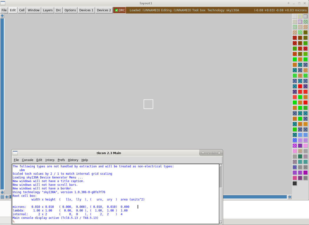
Next we have to open our layout in magic. We can close the xschem window and go to the terminal to open magic.
cd magic
magic -rcfile $PDK_ROOT/$PDK/libs.tech/magic/sky130A.magicrc
7. Open the layout in magic
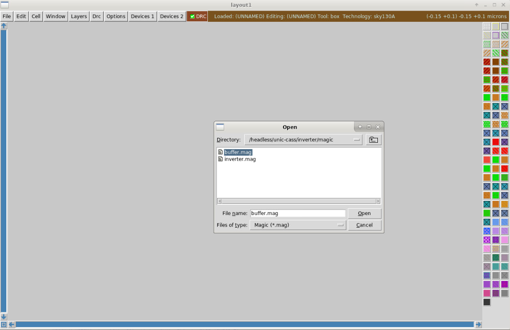
Then, we can open our design by selecting File >> Open. Select buffer.mag and press open
8. Check the design
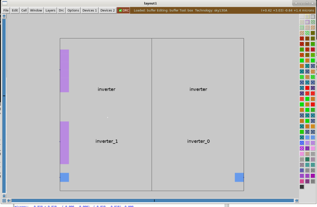
Then the design of the buffer from two inverters will be open. To view the full hierarchy, select Cell >> Expand
9. View the design in full hierarchy
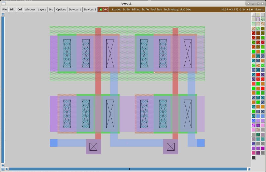
We can display all the layers of the two inverters by selecting Cell >> Expand multiple times.
10. Extract the netlist for LVS
Next, we can extract the netlist by typing the following command in the magic console.
Magic shell
ext all
ext2spice lvs
ext2spice
- The first command
extis to do the extraction of the layout to create thebuffer.extandinverter.ext - The second command
ext2spice lvsis used to set the extraction for LVS - The third command does the extraction. After this step, you will have the netlist for the LVS.
Magic shell output
% ext all
Cell inverter read from current working directory
Scaled magic input cell inverter geometry by factor of 2
Extracting inverter into inverter.ext:
Extracting buffer into buffer.ext:
% ext2spice lvs
% ext2spice
exttospice finished.
%
11. Open the generated netlist
When it finishes successfully, we can close magic and open the generated netlist by running the following command:
cat buffer.spice
Extracted netlist
* NGSPICE file created from buffer.ext - technology: sky130A

.subckt inverter A Y VP VN
X0 Y A VP VP sky130_fd_pr__pfet_01v8 ad=0.5 pd=3 as=0.5 ps=3 w=1 l=0.15
X1 Y A VN VN sky130_fd_pr__nfet_01v8 ad=0.5 pd=3 as=0.5 ps=3 w=1 l=0.15
.ends

.subckt buffer A Y VP VN
Xinverter_0 A inverter_1/A VP VN inverter
Xinverter_1 inverter_1/A Y VP VN inverter
.ends
12. Save the post-layout netlist into netgen directory
Next, we copy this file into the netgen directory with a new name called buffer_layout.spice by running this command:
cp -a buffer.spice ../netgen/buffer_layout.spice
13. Comapare the netlist
We can compare the two files with our own eyes. They look similar or different? Different right? Let’s use netgen to check if they are identical or different. Close the gedit (if any) to run netgen in the terminal.
| Schematic netlist (buffer.spice) | Extracted netlist (buffer_layout.spice) |
|---|---|
| ** sch_path: /home/cass/unic-cass/inverter/buffer.sch .subckt buffer VP A Y VN *.PININFO A:I Y:O VP:B VN:B X1 A net1 VP VN inverter X2 net1 Y VP VN inverter .ends * expanding symbol: inverter.sym # of pins=4 ** sym_path: /home/cass/unic-cass/inverter/inverter.sym ** sch_path: /home/cass/unic-cass/inverter/inverter.sch .subckt inverter A Y VP VN *.PININFO A:I Y:O VP:B VN:B XM1 Y A VN sky130_fd_pr__nfet_01v8 L=0.15 W=1 nf=1 m=1 XM2 Y A VP sky130_fd_pr__pfet_01v8 L=0.15 W=1 nf=1 m=1 .ends .end |
* NGSPICE file created from buffer.ext - technology: sky130A .subckt inverter A Y VP VN X0 Y A VP VP sky130_fd_pr__pfet_01v8 ad=0.5 pd=3 as=0.5 ps=3 w=1 l=0.15 X1 Y A VN VN sky130_fd_pr__nfet_01v8 ad=0.5 pd=3 as=0.5 ps=3 w=1 l=0.15 .ends .subckt buffer Xinverter_0 A inverter_1/A VP VN inverter Xinverter_1 inverter_1/A Y VP VN inverter .ends |
LVS first run
14. View the negen configuration file for Skywater 130nm technology
Running LVS with netgen is very simple, you just need to run netgen with three arguments. The first one and the second one are the two netlists that we created. The third argument is a configuration file that is already available from the PDK. You might have a look at $PDK_ROOT/$PDK/libs.tech/netgen/setup.tcl. It is the netgen setup for sky130A ready to use.
gedit $PDK_ROOT/$PDK/libs.tech/netgen/setup.tcl
libs.tech/netgen/setup.tcl
#---------------------------------------------------------------
# Setup file for netgen LVS
# SkyWater sky130A
#---------------------------------------------------------------
permute default
property default
property parallel none

# Allow override of default #columns in the output format.
catch {format $env(NETGEN_COLUMNS)}

#---------------------------------------------------------------
# For the following, get the cell lists from
# circuit1 and circuit2.
#---------------------------------------------------------------

set cells1 [cells list -all -circuit1]
set cells2 [cells list -all -circuit2]

#-------------------------------------------
# Resistors (except metal)
#-------------------------------------------

set devices {}
lappend devices sky130_fd_pr__res_iso_pw
lappend devices sky130_fd_pr__res_high_po_0p35
lappend devices sky130_fd_pr__res_high_po_0p69
lappend devices sky130_fd_pr__res_high_po_1p41
lappend devices sky130_fd_pr__res_high_po_2p85
lappend devices sky130_fd_pr__res_high_po_5p73
lappend devices sky130_fd_pr__res_high_po
lappend devices sky130_fd_pr__res_xhigh_po_0p35
lappend devices sky130_fd_pr__res_xhigh_po_0p69
lappend devices sky130_fd_pr__res_xhigh_po_1p41
lappend devices sky130_fd_pr__res_xhigh_po_2p85
lappend devices sky130_fd_pr__res_xhigh_po_5p73
lappend devices sky130_fd_pr__res_xhigh_po
lappend devices sky130_fd_pr__res_generic_nd
lappend devices sky130_fd_pr__res_generic_pd
lappend devices sky130_fd_pr__res_generic_nd__hv
lappend devices sky130_fd_pr__res_generic_pd__hv
lappend devices mrdn_hv mrdp_hv

foreach dev $devices {
    if {[lsearch $cells1 $dev] >= 0} {
        permute "-circuit1 $dev" 1 2
        property "-circuit1 $dev" series enable
        property "-circuit1 $dev" series {w critical}
        property "-circuit1 $dev" series {l add}
        property "-circuit1 $dev" parallel enable
        property "-circuit1 $dev" parallel {l critical}
        property "-circuit1 $dev" parallel {w add}
        property "-circuit1 $dev" parallel {value par}
        property "-circuit1 $dev" tolerance {l 0.01} {w 0.01}
        # Ignore these properties
        property "-circuit1 $dev" delete mult
    }
    if {[lsearch $cells2 $dev] >= 0} {
        permute "-circuit2 $dev" 1 2
        property "-circuit2 $dev" series enable
        property "-circuit2 $dev" series {w critical}
        property "-circuit2 $dev" series {l add}
        property "-circuit2 $dev" parallel enable
        property "-circuit2 $dev" parallel {l critical}
        property "-circuit2 $dev" parallel {w add}
        property "-circuit2 $dev" parallel {value par}
        property "-circuit2 $dev" tolerance {l 0.01} {w 0.01}
        # Ignore these properties
        property "-circuit2 $dev" delete mult
    }
}
...
15. Run netgen with two netlist files
Now, we can close gedit and start running the LVS check by using the following command:
cd $HOME/unic-cass/inverter/netgen
netgen -batch lvs "buffer.spice buffer" "buffer_layout.spice buffer" \
    $PDK_ROOT/$PDK/libs.tech/netgen/setup.tcl
The above command will compare the buffer subcircuit in buffer.spice with the buffer subcircuit extracted by magic in buffer_layout.spice
(base) cass@unic-cass:~/unic-cass/inverter/netgen$ netgen -batch lvs "buffer.spice buffer" "buffer_layout.spice buffer" $PDK_ROOT/$PDK/libs.tech/netgen/setup.tcl
Netgen 1.5.272 compiled on Tue Mar  5 23:16:53 UTC 2024
Warning: netgen command 'format' use fully-qualified name '::netgen::format'
Warning: netgen command 'global' use fully-qualified name '::netgen::global'
Reading netlist file buffer.spice
Call to undefined subcircuit inverter
Creating placeholder cell definition.
Call to undefined subcircuit sky130_fd_pr__nfet_01v8
Creating placeholder cell definition.
Call to undefined subcircuit sky130_fd_pr__pfet_01v8
Creating placeholder cell definition.
Reading netlist file buffer_layout.spice
Call to undefined subcircuit sky130_fd_pr__pfet_01v8
Creating placeholder cell definition.
Call to undefined subcircuit sky130_fd_pr__nfet_01v8
Creating placeholder cell definition.

Reading setup file /home/cass/eda/unic-cass/share/pdk/sky130A/libs.tech/netgen/setup.tcl

Model sky130_fd_pr__nfet_01v8 pin 1 == 3
No property as found for device sky130_fd_pr__nfet_01v8
No property ad found for device sky130_fd_pr__nfet_01v8
No property ps found for device sky130_fd_pr__nfet_01v8
No property pd found for device sky130_fd_pr__nfet_01v8
No property mult found for device sky130_fd_pr__nfet_01v8
No property sa found for device sky130_fd_pr__nfet_01v8
No property sb found for device sky130_fd_pr__nfet_01v8
No property sd found for device sky130_fd_pr__nfet_01v8
No property nrd found for device sky130_fd_pr__nfet_01v8
No property nrs found for device sky130_fd_pr__nfet_01v8
No property area found for device sky130_fd_pr__nfet_01v8
No property perim found for device sky130_fd_pr__nfet_01v8
No property topography found for device sky130_fd_pr__nfet_01v8
Model sky130_fd_pr__nfet_01v8 pin 1 == 3
No property mult found for device sky130_fd_pr__nfet_01v8
No property sa found for device sky130_fd_pr__nfet_01v8
No property sb found for device sky130_fd_pr__nfet_01v8
No property sd found for device sky130_fd_pr__nfet_01v8
No property nf found for device sky130_fd_pr__nfet_01v8
No property nrd found for device sky130_fd_pr__nfet_01v8
No property nrs found for device sky130_fd_pr__nfet_01v8
No property area found for device sky130_fd_pr__nfet_01v8
No property perim found for device sky130_fd_pr__nfet_01v8
No property topography found for device sky130_fd_pr__nfet_01v8
Model sky130_fd_pr__pfet_01v8 pin 1 == 3
No property as found for device sky130_fd_pr__pfet_01v8
No property ad found for device sky130_fd_pr__pfet_01v8
No property ps found for device sky130_fd_pr__pfet_01v8
No property pd found for device sky130_fd_pr__pfet_01v8
No property mult found for device sky130_fd_pr__pfet_01v8
No property sa found for device sky130_fd_pr__pfet_01v8
No property sb found for device sky130_fd_pr__pfet_01v8
No property sd found for device sky130_fd_pr__pfet_01v8
No property nrd found for device sky130_fd_pr__pfet_01v8
No property nrs found for device sky130_fd_pr__pfet_01v8
No property area found for device sky130_fd_pr__pfet_01v8
No property perim found for device sky130_fd_pr__pfet_01v8
No property topography found for device sky130_fd_pr__pfet_01v8
Model sky130_fd_pr__pfet_01v8 pin 1 == 3
No property mult found for device sky130_fd_pr__pfet_01v8
No property sa found for device sky130_fd_pr__pfet_01v8
No property sb found for device sky130_fd_pr__pfet_01v8
No property sd found for device sky130_fd_pr__pfet_01v8
No property nf found for device sky130_fd_pr__pfet_01v8
No property nrd found for device sky130_fd_pr__pfet_01v8
No property nrs found for device sky130_fd_pr__pfet_01v8
No property area found for device sky130_fd_pr__pfet_01v8
No property perim found for device sky130_fd_pr__pfet_01v8
No property topography found for device sky130_fd_pr__pfet_01v8
Comparison output logged to file comp.out
Logging to file "comp.out" enabled
Circuit sky130_fd_pr__nfet_01v8 contains no devices.
Circuit sky130_fd_pr__pfet_01v8 contains no devices.

Contents of circuit 1:  Circuit: 'inverter'
Circuit inverter contains 2 device instances.
  Class: sky130_fd_pr__nfet_01v8 instances:   1
  Class: sky130_fd_pr__pfet_01v8 instances:   1
Circuit contains 6 nets.
Contents of circuit 2:  Circuit: 'inverter'
Circuit inverter contains 2 device instances.
  Class: sky130_fd_pr__nfet_01v8 instances:   1
  Class: sky130_fd_pr__pfet_01v8 instances:   1
Circuit contains 4 nets.

Circuit 1 contains 2 devices, Circuit 2 contains 2 devices.
Circuit 1 contains 6 nets,    Circuit 2 contains 4 nets. *** MISMATCH ***

  Flattening non-matched subcircuits inverter inverter

Flattening instances of inverter in file buffer.spice
Flattening instances of inverter in file buffer_layout.spice

Contents of circuit 1:  Circuit: 'buffer'
Circuit buffer contains 4 device instances.
  Class: sky130_fd_pr__nfet_01v8 instances:   2
  Class: sky130_fd_pr__pfet_01v8 instances:   2
Circuit contains 9 nets.
Contents of circuit 2:  Circuit: 'buffer'
Circuit buffer contains 4 device instances.
  Class: sky130_fd_pr__nfet_01v8 instances:   2
  Class: sky130_fd_pr__pfet_01v8 instances:   2
Circuit contains 5 nets.

Circuit 1 contains 4 devices, Circuit 2 contains 4 devices.
Circuit 1 contains 9 nets,    Circuit 2 contains 5 nets. *** MISMATCH ***


Final result:
Netlists do not match.
Logging to file "comp.out" disabled
LVS Done.
We can see that the two circuits do not match. Netgen said that Circuit 1 has 9 nets, while Circuit 2 has only 5 nets. Now we need to look into the details to see what happens.
16. Review the outputs
Open the comp.out file in the netgen directory to see the details of the LVS.
gedit comp.out
Looking at the detailed report from netgen, it is easily noticed that the Circuit 1 (generated by xschem) the pfet and nfet only have three pins while the ones in the layout have four pins.
The problem is that we are using nfet3 and pfet3 in xschem and by default the pin 4 in nfet3 and pfet3 symbols are not connected. However, in the layout, we connect the subtrate (pin 4) of the transistors nfet and pfet to the port VN and VP respectively. Obviously, the two circuits are mismatched.
17. Two possible solutions for the above LVS violations
First, you can modify the inverter netlist by using the nfet and pfet instead of nfet3 and pfet3. Then you explicitly connect the subtract to the corresponding VN and VP terminal. This is an exercise for you.
The second solution is to set the body of these transistors to the correct terminal. We show this solution in the following steps
LVS second run
18. Open the schematic in Xschem
We have to open the schematic in xschem again by this command:
cd $HOME/unic-cass/inverter
xschem buffer.xschem
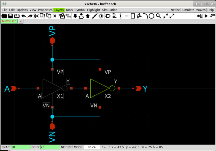
19. Go to the inverter schematic
Next, you click on one of the inverters then press the keyboard shortcut e to go to the inverter schematic.
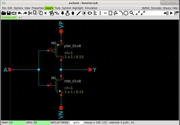
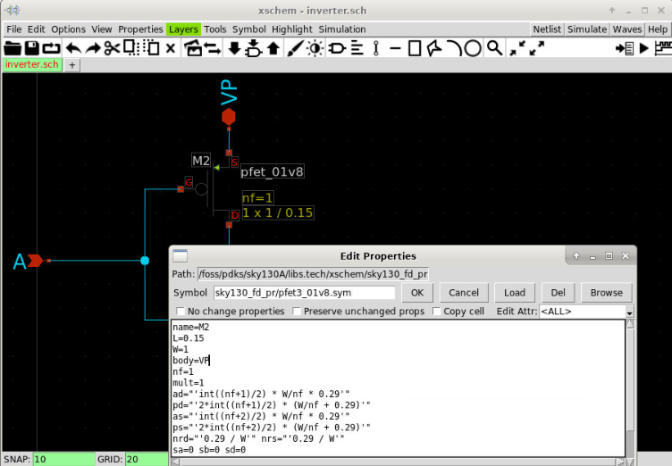
20. Set the body of pfet to connect to VP
Next, we select the pfet and press the keyboard shortcut q to change its attributes. Add the line body=VP as the following and click OK.
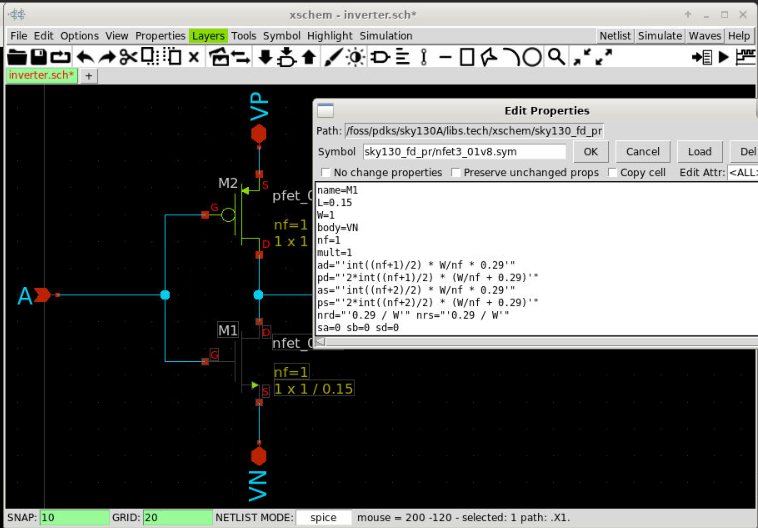
21. Set the body of nfet to connect to VN
We repeat the previous step with the nfet and the body should be VN.
22. Save the inverter schematic and go to the buffer schematic
Then we can save the schematic and go back to the buffer design by pressing ctrl + e.
23. Generate new netlist
In the buffer design, we generate the netlist by clicking on the netlist button. We check if our changes have been reflected by selecting Simulation >> Edit Netlist.
Note Please remember to change the netlist directory by
Simulation >> Set Netlist Dirto the negen directory before generating the netlist.
Xschem spice netlist: bufffer.spice
** sch_path: /home/cass/unic-cass/inverter/buffer.sch
.subckt buffer VP A Y VN
*.PININFO A:I Y:O VP:B VN:B
X1 A net1 VP VN inverter
X2 net1 Y VP VN inverter
.ends

* expanding   symbol:  inverter.sym # of pins=4
** sym_path: /home/cass/unic-cass/inverter/inverter.sym
** sch_path: /home/cass/unic-cass/inverter/inverter.sch
.subckt inverter A Y VP VN
*.PININFO A:I Y:O VP:B VN:B
XM1 Y A VN VN sky130_fd_pr__nfet_01v8 L=0.15 W=1 nf=1 m=1
XM2 Y A VP VP sky130_fd_pr__pfet_01v8 L=0.15 W=1 nf=1 m=1
.ends

.end
24. Re-run the LVS
We run the LVS again using the following command:
netgen -batch lvs "buffer.spice buffer" "buffer_layout.spice buffer" \
    $PDK_ROOT/$PDK/libs.tech/netgen/setup.tcl
Netgen 1.5.272 compiled on Tue Mar  5 23:16:53 UTC 2024
Warning: netgen command 'format' use fully-qualified name '::netgen::format'
Warning: netgen command 'global' use fully-qualified name '::netgen::global'
Reading netlist file buffer.spice
Call to undefined subcircuit inverter
Creating placeholder cell definition.
Call to undefined subcircuit sky130_fd_pr__nfet_01v8
Creating placeholder cell definition.
Call to undefined subcircuit sky130_fd_pr__pfet_01v8
Creating placeholder cell definition.
Reading netlist file buffer_layout.spice
Call to undefined subcircuit sky130_fd_pr__pfet_01v8
Creating placeholder cell definition.
Call to undefined subcircuit sky130_fd_pr__nfet_01v8
Creating placeholder cell definition.

Reading setup file /home/cass/eda/unic-cass/share/pdk/sky130A/libs.tech/netgen/setup.tcl

Model sky130_fd_pr__nfet_01v8 pin 1 == 3
No property as found for device sky130_fd_pr__nfet_01v8
No property ad found for device sky130_fd_pr__nfet_01v8
No property ps found for device sky130_fd_pr__nfet_01v8
No property pd found for device sky130_fd_pr__nfet_01v8
No property mult found for device sky130_fd_pr__nfet_01v8
No property sa found for device sky130_fd_pr__nfet_01v8
No property sb found for device sky130_fd_pr__nfet_01v8
No property sd found for device sky130_fd_pr__nfet_01v8
No property nrd found for device sky130_fd_pr__nfet_01v8
No property nrs found for device sky130_fd_pr__nfet_01v8
No property area found for device sky130_fd_pr__nfet_01v8
No property perim found for device sky130_fd_pr__nfet_01v8
No property topography found for device sky130_fd_pr__nfet_01v8
Model sky130_fd_pr__nfet_01v8 pin 1 == 3
No property mult found for device sky130_fd_pr__nfet_01v8
No property sa found for device sky130_fd_pr__nfet_01v8
No property sb found for device sky130_fd_pr__nfet_01v8
No property sd found for device sky130_fd_pr__nfet_01v8
No property nf found for device sky130_fd_pr__nfet_01v8
No property nrd found for device sky130_fd_pr__nfet_01v8
No property nrs found for device sky130_fd_pr__nfet_01v8
No property area found for device sky130_fd_pr__nfet_01v8
No property perim found for device sky130_fd_pr__nfet_01v8
No property topography found for device sky130_fd_pr__nfet_01v8
Model sky130_fd_pr__pfet_01v8 pin 1 == 3
No property as found for device sky130_fd_pr__pfet_01v8
No property ad found for device sky130_fd_pr__pfet_01v8
No property ps found for device sky130_fd_pr__pfet_01v8
No property pd found for device sky130_fd_pr__pfet_01v8
No property mult found for device sky130_fd_pr__pfet_01v8
No property sa found for device sky130_fd_pr__pfet_01v8
No property sb found for device sky130_fd_pr__pfet_01v8
No property sd found for device sky130_fd_pr__pfet_01v8
No property nrd found for device sky130_fd_pr__pfet_01v8
No property nrs found for device sky130_fd_pr__pfet_01v8
No property area found for device sky130_fd_pr__pfet_01v8
No property perim found for device sky130_fd_pr__pfet_01v8
No property topography found for device sky130_fd_pr__pfet_01v8
Model sky130_fd_pr__pfet_01v8 pin 1 == 3
No property mult found for device sky130_fd_pr__pfet_01v8
No property sa found for device sky130_fd_pr__pfet_01v8
No property sb found for device sky130_fd_pr__pfet_01v8
No property sd found for device sky130_fd_pr__pfet_01v8
No property nf found for device sky130_fd_pr__pfet_01v8
No property nrd found for device sky130_fd_pr__pfet_01v8
No property nrs found for device sky130_fd_pr__pfet_01v8
No property area found for device sky130_fd_pr__pfet_01v8
No property perim found for device sky130_fd_pr__pfet_01v8
No property topography found for device sky130_fd_pr__pfet_01v8
Comparison output logged to file comp.out
Logging to file "comp.out" enabled
Circuit sky130_fd_pr__nfet_01v8 contains no devices.
Circuit sky130_fd_pr__pfet_01v8 contains no devices.

Contents of circuit 1:  Circuit: 'inverter'
Circuit inverter contains 2 device instances.
  Class: sky130_fd_pr__nfet_01v8 instances:   1
  Class: sky130_fd_pr__pfet_01v8 instances:   1
Circuit contains 4 nets.
Contents of circuit 2:  Circuit: 'inverter'
Circuit inverter contains 2 device instances.
  Class: sky130_fd_pr__nfet_01v8 instances:   1
  Class: sky130_fd_pr__pfet_01v8 instances:   1
Circuit contains 4 nets.

Circuit 1 contains 2 devices, Circuit 2 contains 2 devices.
Circuit 1 contains 4 nets,    Circuit 2 contains 4 nets.


Contents of circuit 1:  Circuit: 'buffer'
Circuit buffer contains 2 device instances.
  Class: inverter              instances:   2
Circuit contains 5 nets.
Contents of circuit 2:  Circuit: 'buffer'
Circuit buffer contains 2 device instances.
  Class: inverter              instances:   2
Circuit contains 5 nets.

Circuit 1 contains 2 devices, Circuit 2 contains 2 devices.
Circuit 1 contains 5 nets,    Circuit 2 contains 5 nets.


Final result:
Circuits match uniquely.
.
Logging to file "comp.out" disabled
LVS Done.
25. LVS runs successfully
Clearly, there is no mismatch as before. We can confirm by viewing the detailed reports from netgen in comp.out.
File: comp.out
Circuit 1 cell sky130_fd_pr__nfet_01v8 and Circuit 2 cell sky130_fd_pr__nfet_01v8 are black boxes.
Warning: Equate pins:  cell sky130_fd_pr__nfet_01v8 is a placeholder, treated as a black box.
Warning: Equate pins:  cell sky130_fd_pr__nfet_01v8 is a placeholder, treated as a black box.

Subcircuit pins:
Circuit 1: sky130_fd_pr__nfet_01v8         |Circuit 2: sky130_fd_pr__nfet_01v8
-------------------------------------------|-------------------------------------------
1                                          |1
2                                          |2
3                                          |3
4                                          |4
---------------------------------------------------------------------------------------
Cell pin lists are equivalent.
Device classes sky130_fd_pr__nfet_01v8 and sky130_fd_pr__nfet_01v8 are equivalent.

Circuit 1 cell sky130_fd_pr__pfet_01v8 and Circuit 2 cell sky130_fd_pr__pfet_01v8 are black boxes.
Warning: Equate pins:  cell sky130_fd_pr__pfet_01v8 is a placeholder, treated as a black box.
Warning: Equate pins:  cell sky130_fd_pr__pfet_01v8 is a placeholder, treated as a black box.

Subcircuit pins:
Circuit 1: sky130_fd_pr__pfet_01v8         |Circuit 2: sky130_fd_pr__pfet_01v8
-------------------------------------------|-------------------------------------------
1                                          |1
2                                          |2
3                                          |3
4                                          |4
---------------------------------------------------------------------------------------
Cell pin lists are equivalent.
Device classes sky130_fd_pr__pfet_01v8 and sky130_fd_pr__pfet_01v8 are equivalent.

Subcircuit summary:
Circuit 1: inverter                        |Circuit 2: inverter
-------------------------------------------|-------------------------------------------
sky130_fd_pr__nfet_01v8 (1)                |sky130_fd_pr__nfet_01v8 (1)
sky130_fd_pr__pfet_01v8 (1)                |sky130_fd_pr__pfet_01v8 (1)
Number of devices: 2                       |Number of devices: 2
Number of nets: 4                          |Number of nets: 4
---------------------------------------------------------------------------------------
Netlists match uniquely.

Subcircuit pins:
Circuit 1: inverter                        |Circuit 2: inverter
-------------------------------------------|-------------------------------------------
Y                                          |Y
A                                          |A
VP                                         |VP
VN                                         |VN
---------------------------------------------------------------------------------------
Cell pin lists are equivalent.
Device classes inverter and inverter are equivalent.

Subcircuit summary:
Circuit 1: buffer                          |Circuit 2: buffer
-------------------------------------------|-------------------------------------------
inverter (2)                               |inverter (2)
Number of devices: 2                       |Number of devices: 2
Number of nets: 5                          |Number of nets: 5
---------------------------------------------------------------------------------------
Netlists match uniquely.

Subcircuit pins:
Circuit 1: buffer                          |Circuit 2: buffer
-------------------------------------------|-------------------------------------------
VP                                         |VP
VN                                         |VN
A                                          |A
Y                                          |Y
---------------------------------------------------------------------------------------
Cell pin lists are equivalent.
Device classes buffer and buffer are equivalent.

Final result: Circuits match uniquely.
Voila! The report tells us that the two devices are equivalent.
What’s next?
LVS passed is a good sign that your schematic and your layout are equivalent. However, it might not tell you about the important characteristics in analog design. You should run the post layout spice simulation with the parasitic extraction to verify that the parasitic after layout do not affect your design very much.