3.2 Spice Simulation using IHP SG130 PDK with Xscheme and NGSpice
This section introduces the spice simulation with Xscheme and NGSpice
3.1. IHP Open PDK Simulation Model
Transistor Models are written in Verilog-A
- Compiled by OpenVAF before used
Use corner .lib for simulation
-
cornerHBT.lib
-
MOS model: cornerMOShv/lv.lib
-
Resistor models: cornerRES.lib
Abbreviation
-
mod: model
-
parm: parameter of the model
-
stat: statistical model
-
mismatch: local statistical model
ihp-sg13g2/libs.tech/ngspice
.
├── models
│   ├── capacitors_mod.lib
│   ├── capacitors_stat.lib
│   ├── cornerCAP.lib
│   ├── cornerHBT.lib
│   ├── cornerMOShv/lv.lib
│   ├── cornerRES.lib
│   ├── diodes.lib
│   ├── resistors_mod[_mismatch,stat].lib
│   ├── sg13g2_bondpad.lib
│   ├── sg13g2_esd.lib
│   ├── sg13g2_hbt_mod[_mismatch,stat].lib
│   ├── sg13g2_moshv/lv_mismatch.lib
│   ├── sg13g2_moshv/lv_mod.lib
│   ├── sg13g2_moshv/lv_mod_mismatch.lib
│   ├── sg13g2_moshv/lv_parm.lib
│   ├── sg13g2_moshv/lv_stat.lib
│   ├── sg13g2_svaricaphv_mod.lib
│   ├── sg13g2_svaricaphv_mod_mismatch.lib
└── osdi // compiled models
    ├── mosvar.osdi
    ├── psp103_nqs.osdi
    └── r3_cmc.osdi
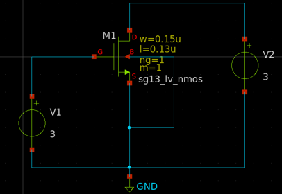
3.2. Create NMOS test circuits in Xscheme
Create the NMOS test circuits with the following components
xscheme_library/devices
V1 & V2: vsource.sym
GND: gnd.sym
sg13g2 devices
M1: sg13_lv_nmos.sym
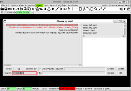
Change library
- Click on the library name on the left
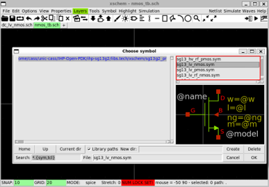
- Can use
Home/Up/Current_dirto go back to the default library list or the folder with the symbols
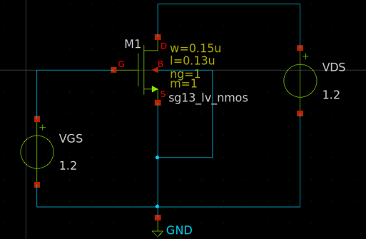
3.3. Change the Instances’ name
Change the name of each components by selecting it and pressing q
-
V1 => VGS
-
V2 => VDS
Final circuit as follows.
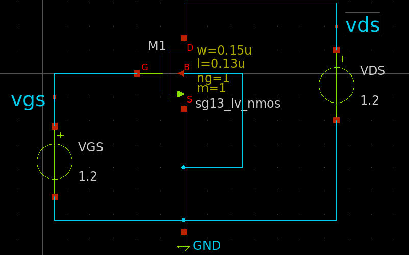
3.4. Insert the Lab Pin
This is for displaying the pin signals on the waveform
- Create
lab_pinsymbols forVDSandVGSsignals as follows.
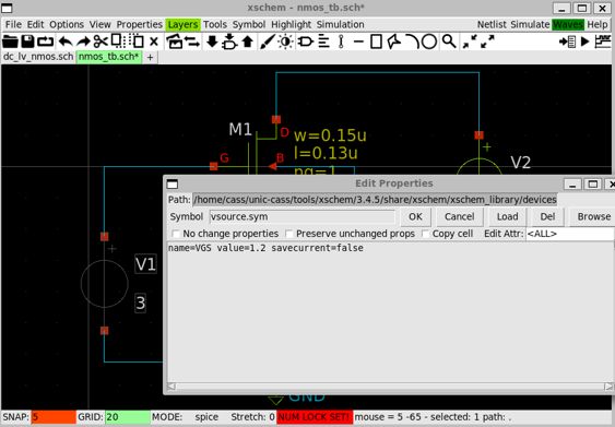
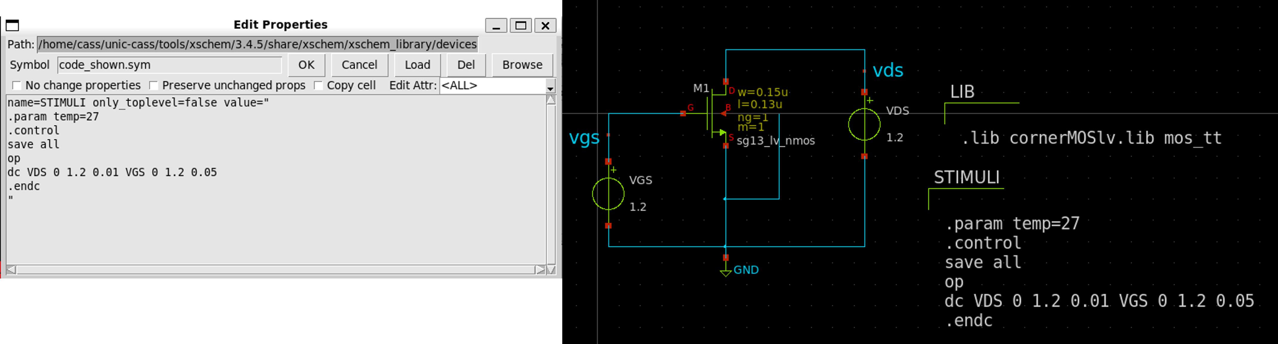
3.5. Setup the Library
Use cornerMOSlv.lib and mos_tt section
- Insert a
code_shown.syminto the schematic and modify its properties as follows
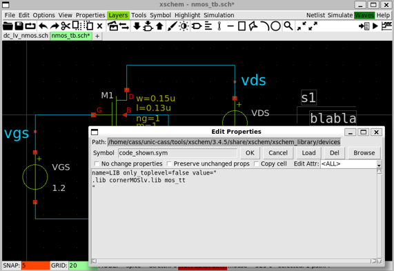
- Spice syntax:
.lib <lib_filename> <lib_section>
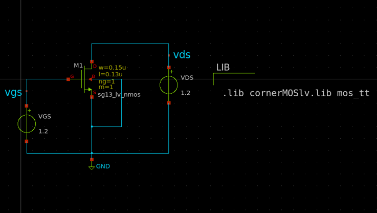
3.6. Setup the Simulation
We need to sweep the VGS and VDS from 0 to 1.2V
- Insert a
code_shown.symand change its properties as follows.
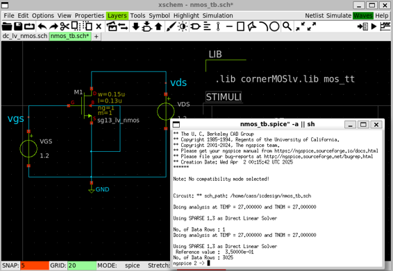
3.7. Generate Netlist and Run the Simulation
-
Click on
Netlistbutton to generate the netlist -
Click on
Simulation»Edit Netlistto view the netlist -
Click on
Simulatebutton to start the simulation
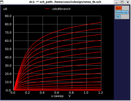
3.8. Plot the Waveform
- In
NGSpicesimulation terminal, displaying the nodes in the schematic by enterringdisplaycommand
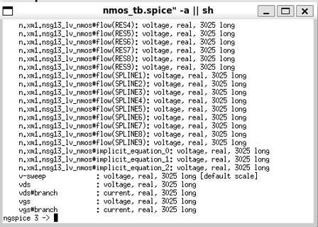
-
NGSpice annotates the current as
<node_name>#branch -
Plot IDS by enterring
plot-vds#branchcommand