3.3 Inverter Schematic and Simulation in Xscheme
This section introduces an example how to make an inverter’s schematic and simulate it.
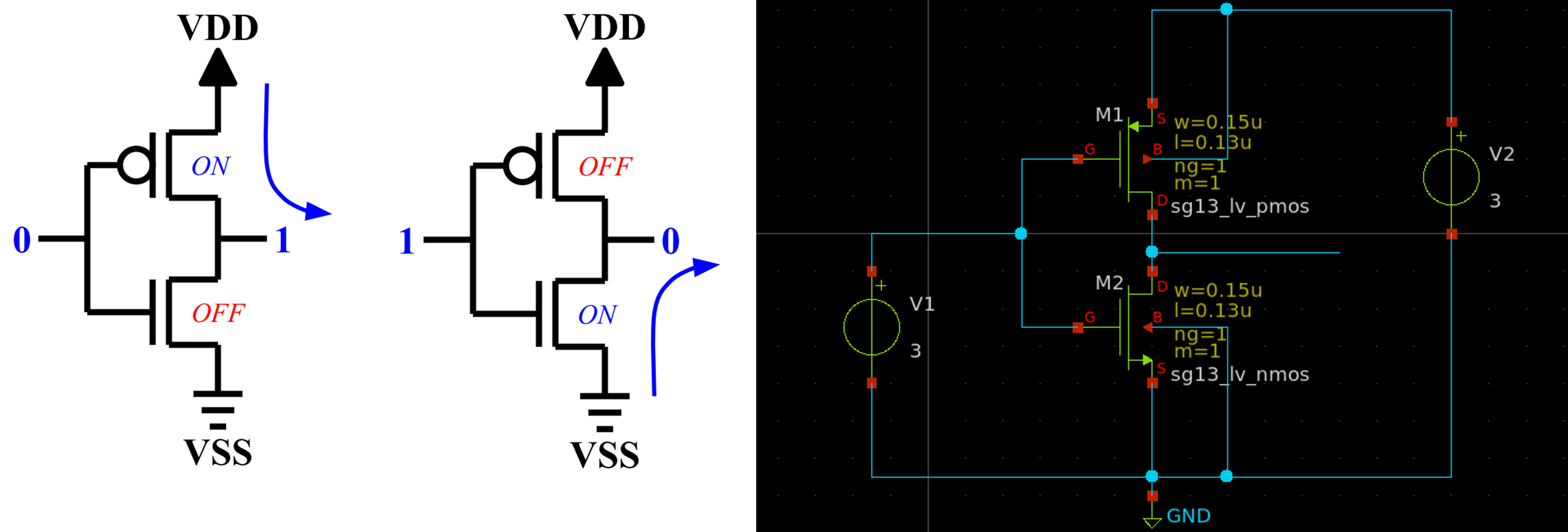
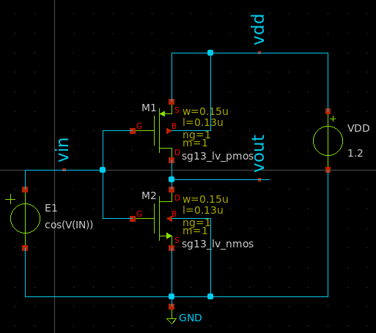
1. Create an Inverter Schematic in Xscheme
This requires two transistors, PMOS and NMOS.
-
M1: sg13_lv_pmos
-
M2: sg13_lv_nmos
-
V1, V2: vsource.sym
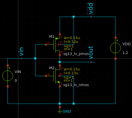
The overview schematic of an inverter is illustrated as follows.
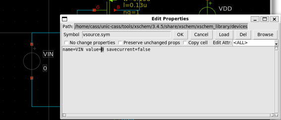
2. Create the Power Supply and Input Signal
With the above schematic, change the voltage source as follows.
-
Change
V1intoVINwithvalue=0 -
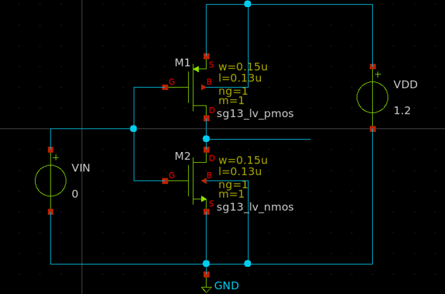
Change
V2intoVDDwithvalue=1.2
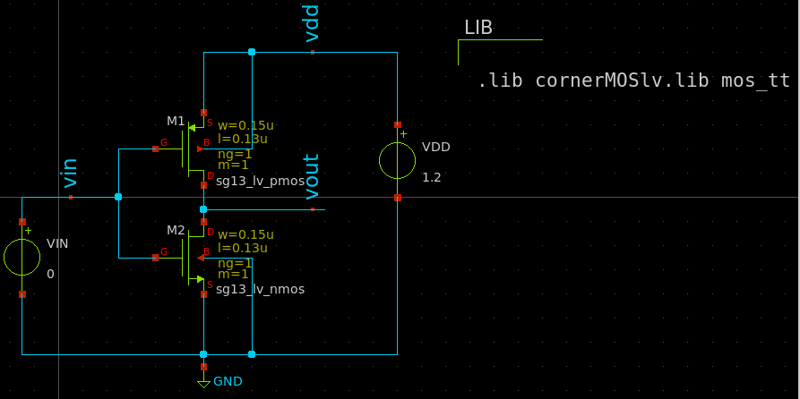
The final schematic is shown as follows.
3. Add the Lab Pins
-
Create the lab pins for the input signal
vinand the output signalvoutby using thelab_pin.sym -
Similarly, create a lab pin for the power supply
vdd
4. Setup the Library
- Use
cornerMOSlv.libandmos_ttsection and insert acode_shown.syminto the schematic and modify its properties as follows.
.lib cornerMOSlv.lib mos_tt
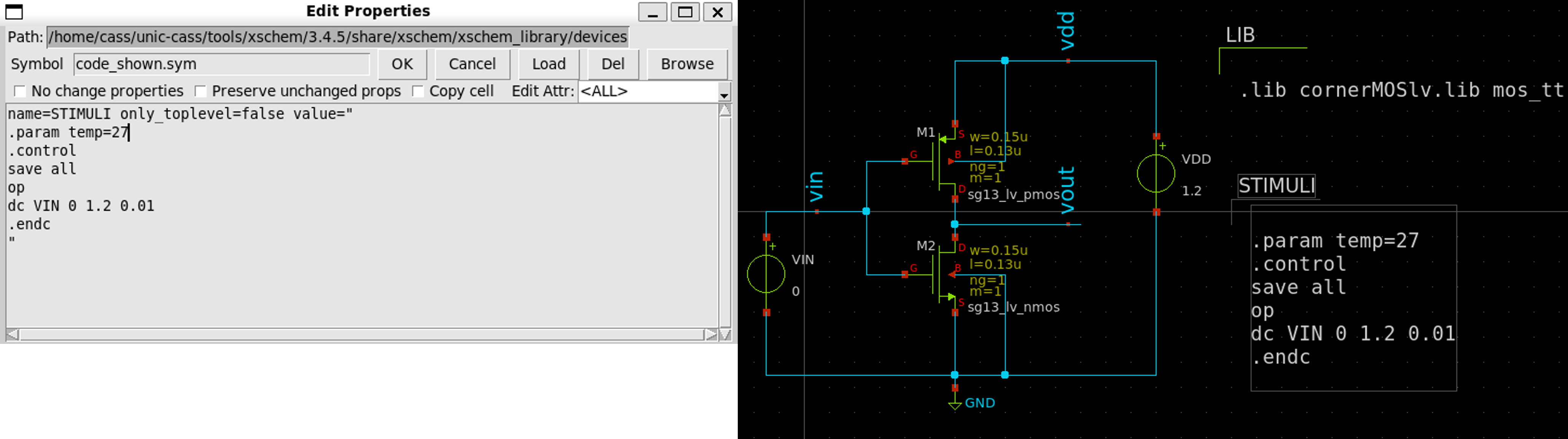
5. Setup the Simulation
We need to sweep the VGS and VDS from 0 to 1.2V.
- Insert a
code_shown.symand change its name intoSTIMULIand its properties as follows.
.param temp=27
.control
save all
op
dc VIN 0 1.2 0.01
.endc
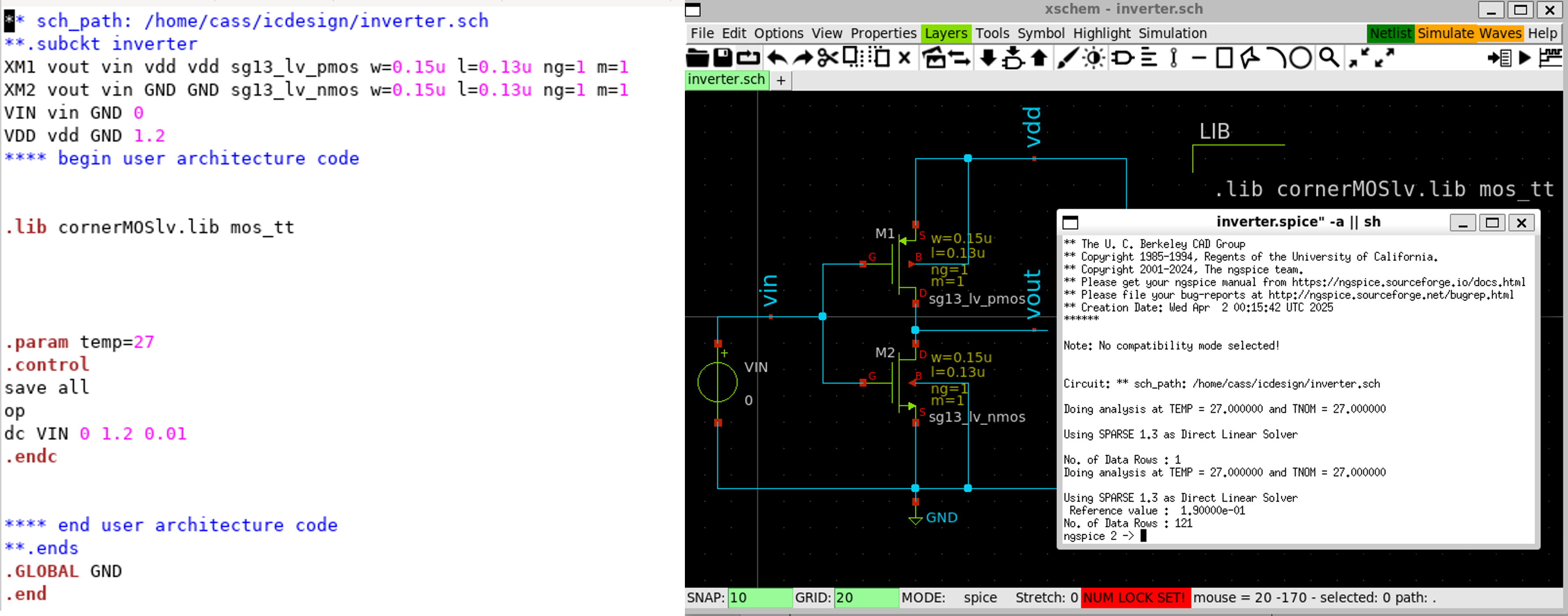
6. Generate Netlist and Run the Simulation
-
Click on
Netlistbutton to generate the netlist -
Click on
Simulation»Edit Netlistto view the netlist -
Click on
Simulatebutton to start the simulation
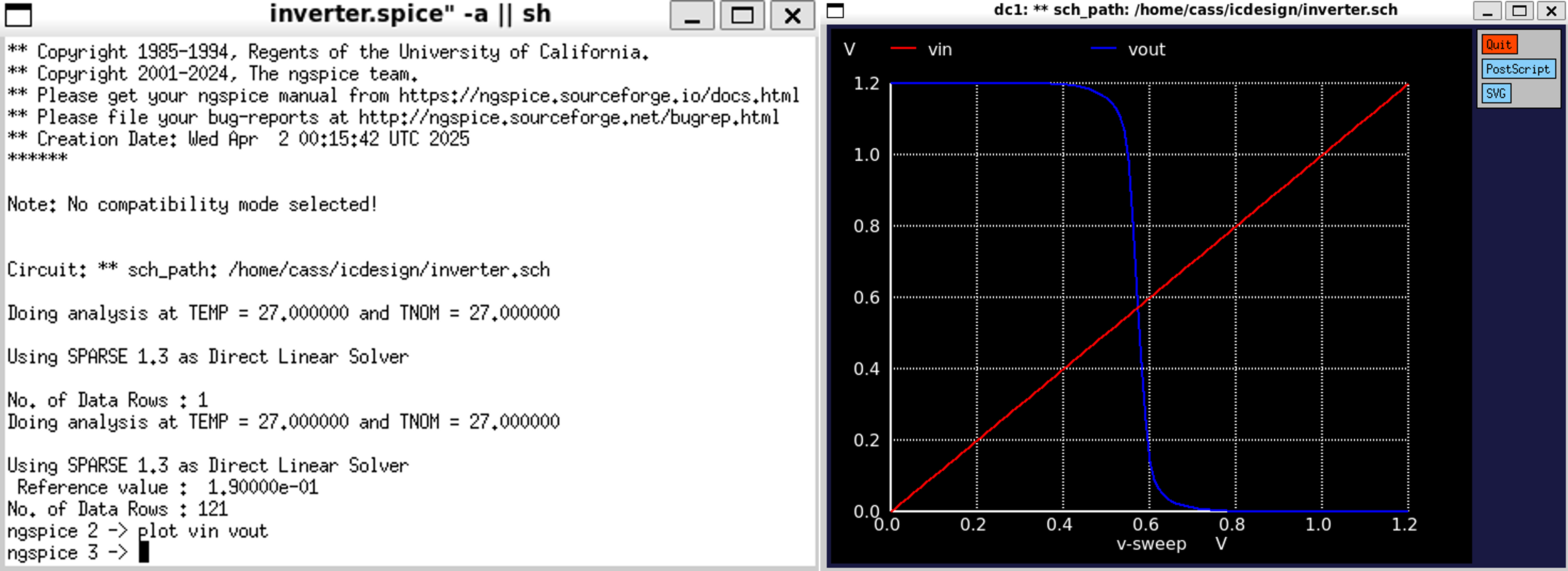
7. Plot the Waveform
- Plot the voltage of
vinandvoutby running the following command inngspiceshell:
plot vin vout
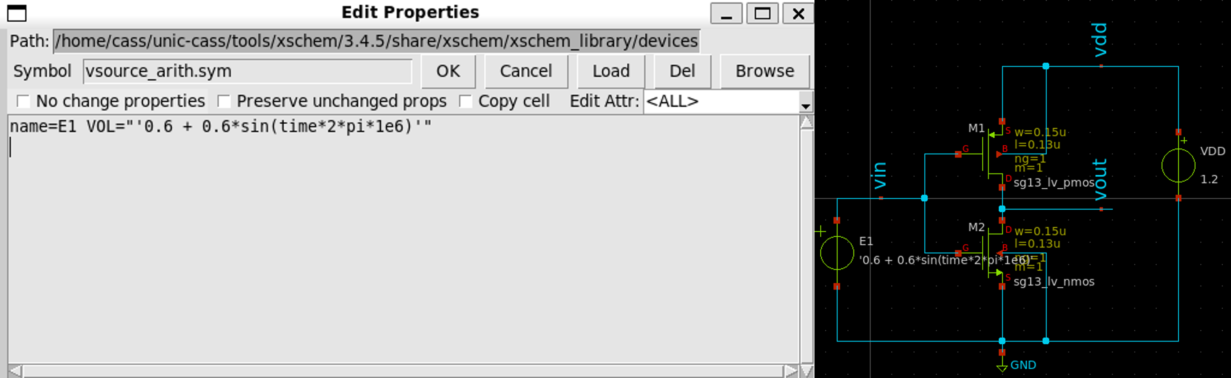
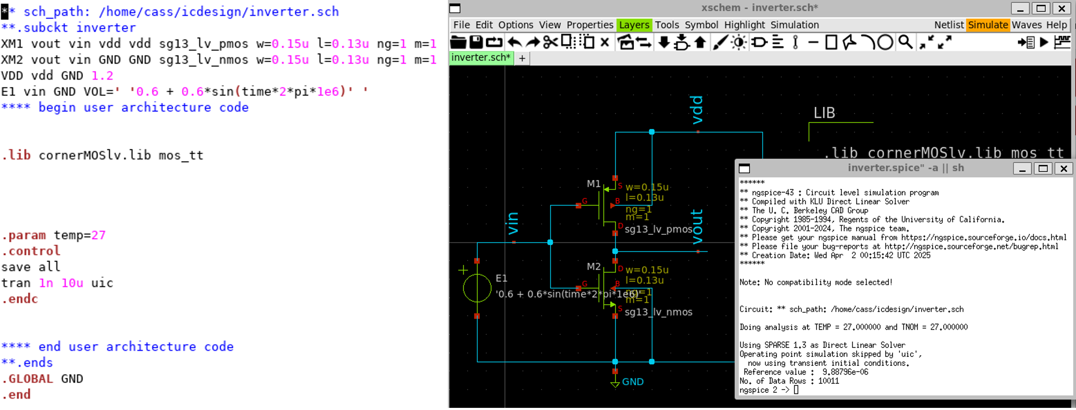
8. Modify the Circuit for Transient Simulation
-
Based on the schematic from the previous section, delete
VINsymbol (select it, then pressdeletekey) -
Insert
vsource_arithm.symand connect the wires, respectively.
- Change
E1source’s properties as follows.
9. Change the Simulation Type
- Change the simulation type from
DCtotransientby editing theSTIMULIas follows.
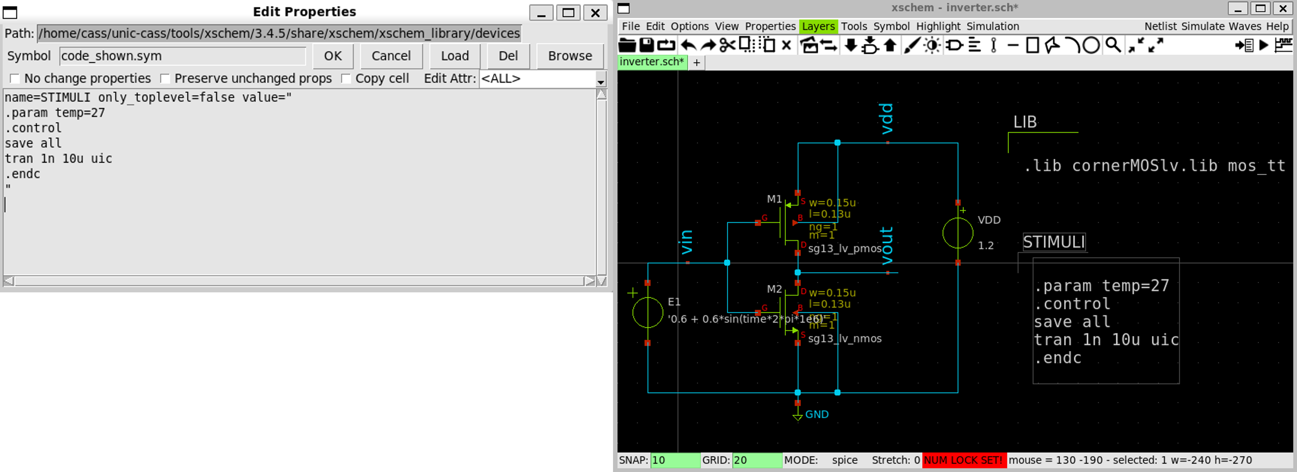
10. Generate Netlist again and Run the Simulation
-
Click on
Netlistbutton to generate the netlist -
Click on
Simulation»Edit Netlistto view the netlist -
Click on
Simulatebutton to start the simulation
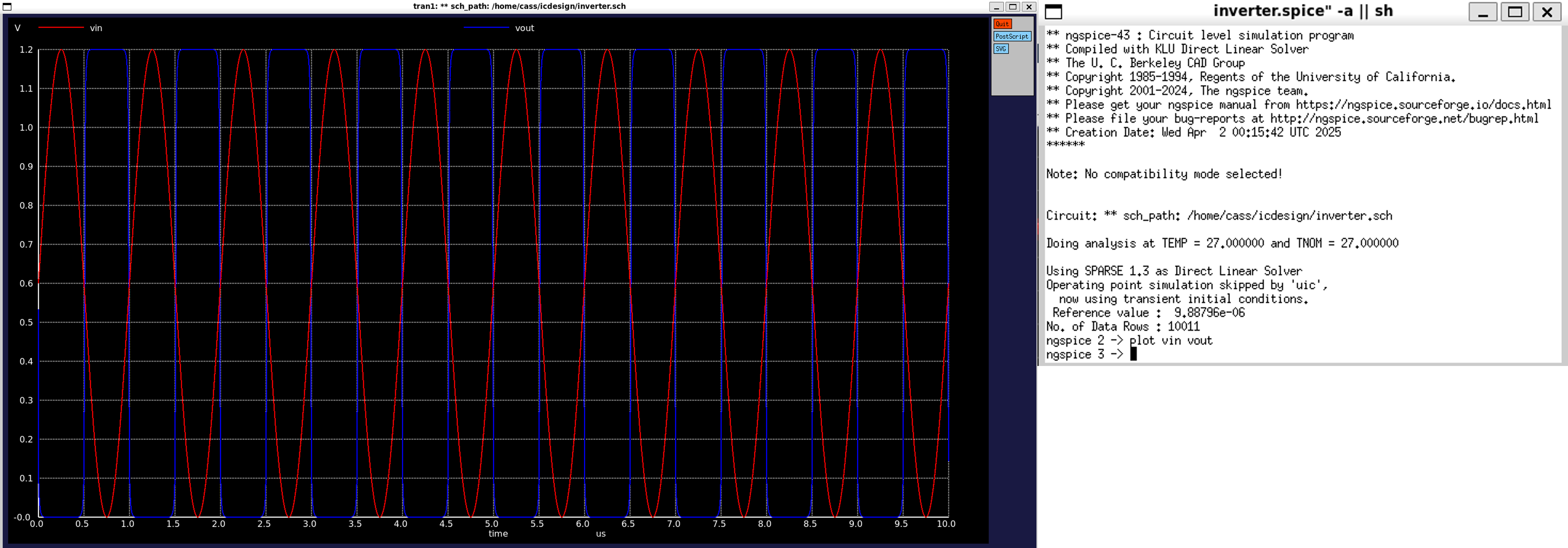
11. Plot the Waveform
- Plot the voltage of
vinandvoutby typing the following command inngspiceshell.
plot vin vout