3.4 Creating the Inverter’s Subcircuit and Symbol in Xschem
This section introduces how to create the inverter as a subcircuit and make its symbol with Xschem.
1. Inverter as Subcircuit
Create an inverter schematic in Xcheme
-
Input:
A(ipin.sym) -
Output:
Y(opin.sym) -
Power supply:
VDD(iopin.sym) -
Ground:
VSS(iopin.sym)
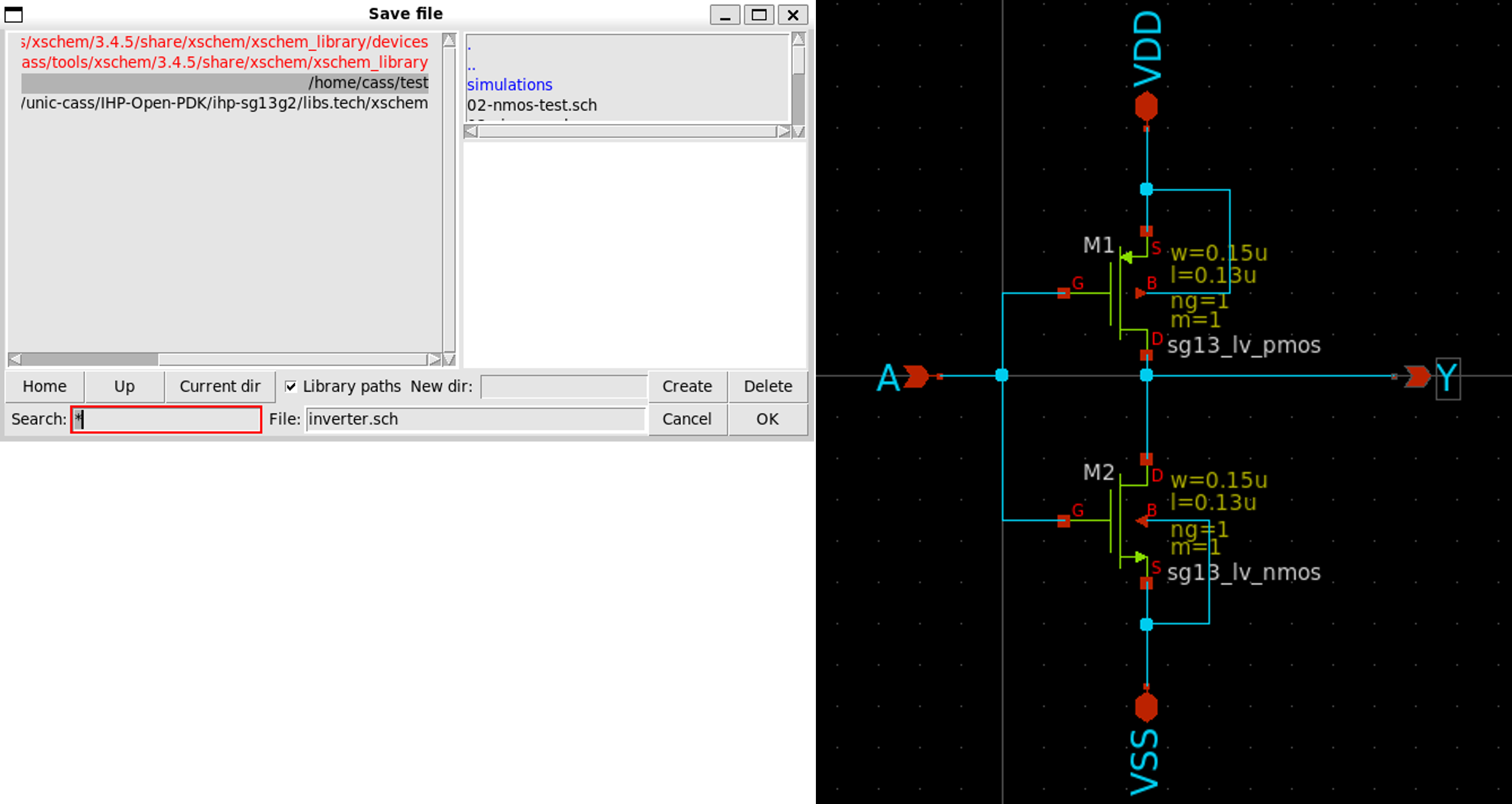
Save the schematic by selecting File » Save As » inverter.sch
Next, we create the symbol for the inverter.
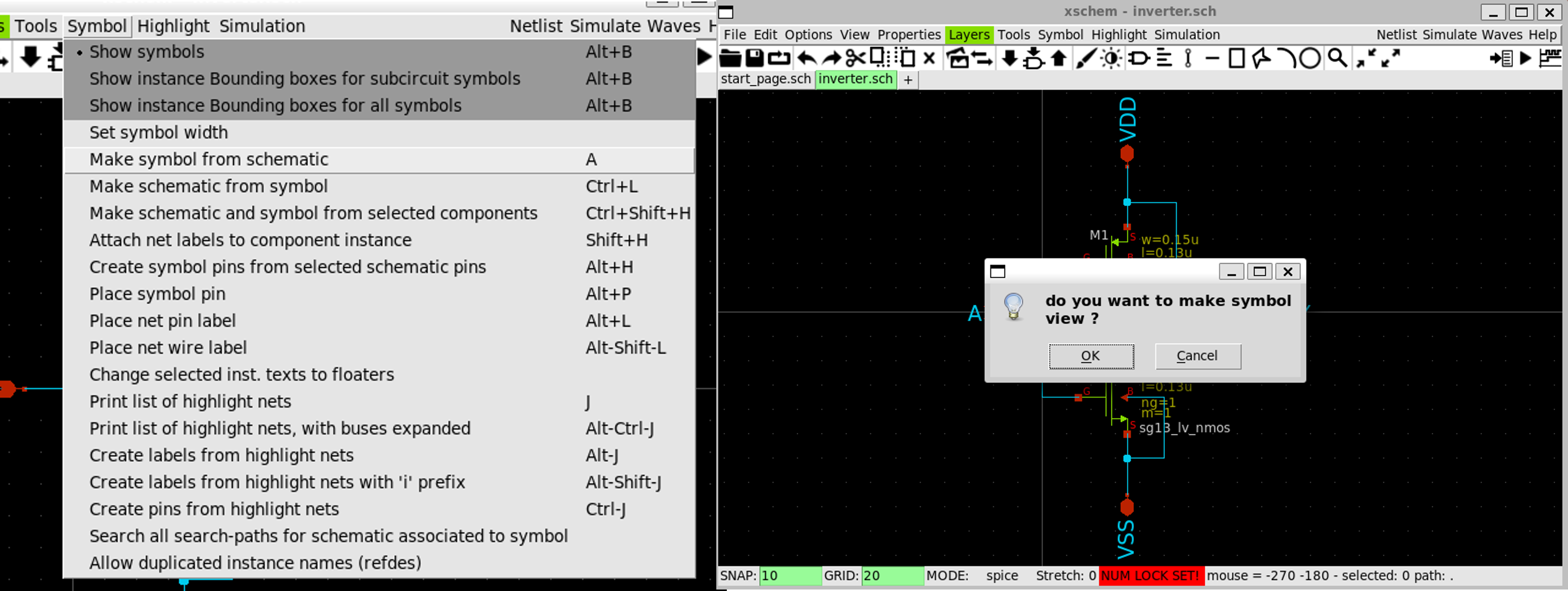
2. Create Symbol
Create a symbol by selecting Symbol » Make symbol from schematic
-
Click
OKon the dialogDo you want to make symbol view -
A new file named
inverter.symwill be create in the same directory
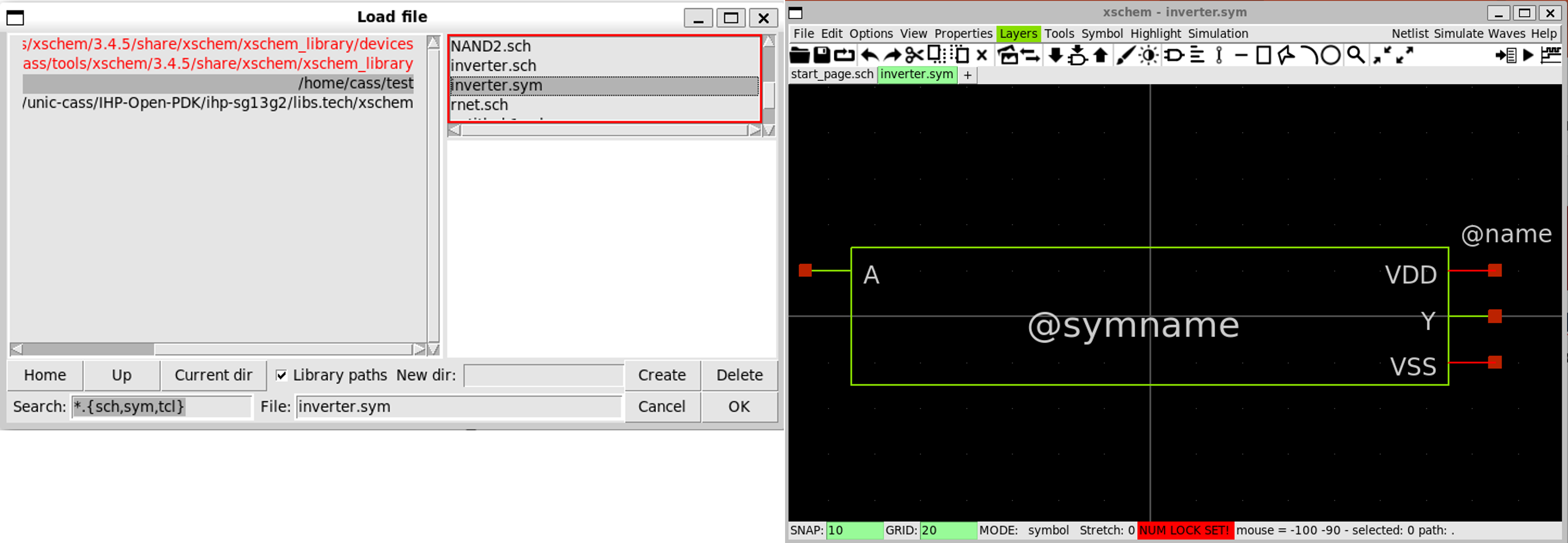
The next step is to edit this symbol file.
3. Edit the Symbol
Click on File » Open then select inverter.sym in the open dialog
- You might need to choose the correct directory containing the symbol file first
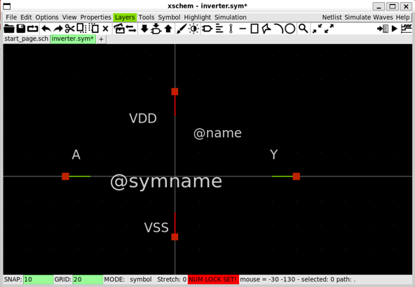
4. Make the Inverter Shape
-
Delete the rectangle by selecting the lines and press
delete. -
Move the pins including
A,Y,VDD,VSSas the following (Please note the center of the drawing, this is important.)
- Press
Lmultiple times to draw the triangle shape for the inverters as follows.
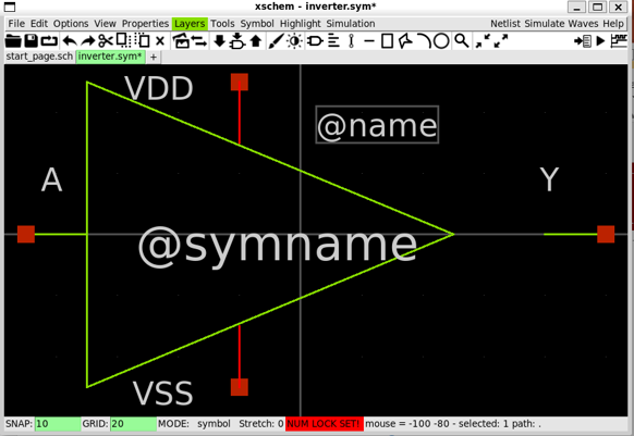
-
Move
VDDandVSSpins toward the triangle. -
In this step, we might need to change the snape size. Change the snape size by pressing
gto decrease orShift+gto increase its size.
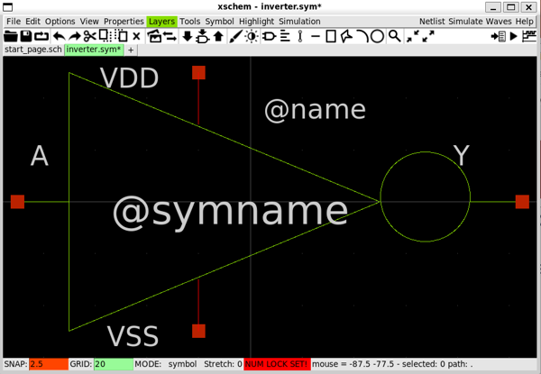
-
Draw the triangle by clicking on two points and size the circle as you want
-
Move the circle and other component if necessary
-
Click on save when done.
5. Create a Testbench for Inverter
-
Create a new schematic by selecting
File»Create new window/tab -
Insert a new instance by selecting
Tools»Insert Symboland selecting the folder with theinverter.sym -
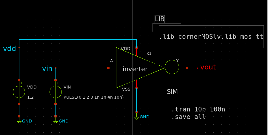
Create a new schematic as follows.
VDD,VIN:vsource.sym
vdd,vin,vout:lab_pin.sym
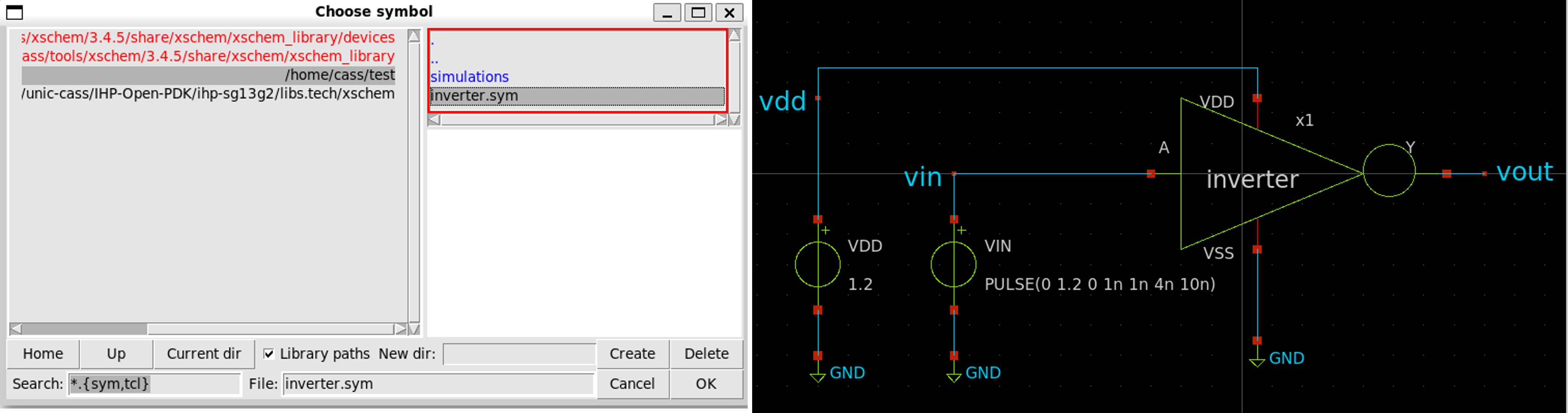
- Next, setup the library and simulation options as follows.
6. Run NGSpice in Batch Mode
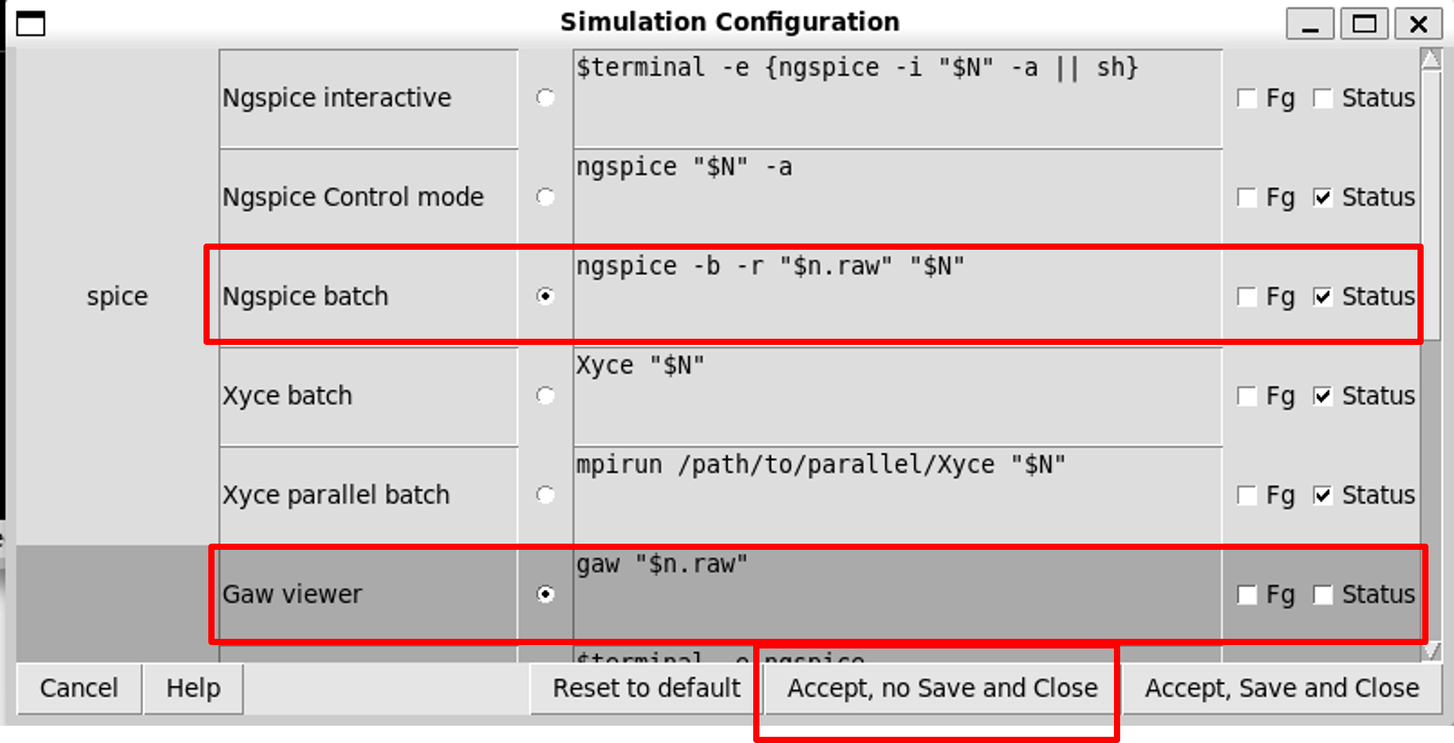
- Click on
Simulation»Configure simulators & tools, selectingNgspice batchandGaw viewer, then click onAccept, no Save and Close.
7. Generate Netlist and Simulate
-
Click on
Netlistbutton to generate the netlist -
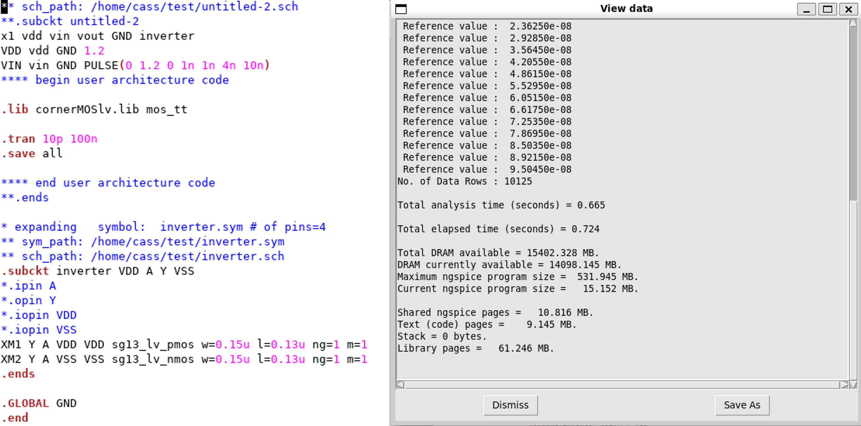
Click on
Simulation»Edit Netlistto view the netlist -
Click on
Simulatebutton to start the simulation
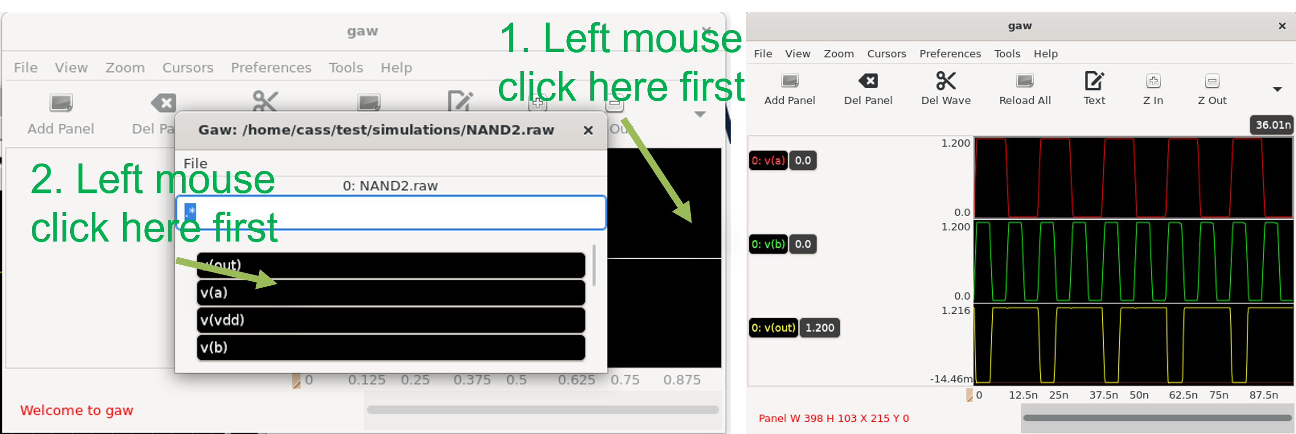
8. View the Waveform
We use Xscheme-GAW to view the waveform.
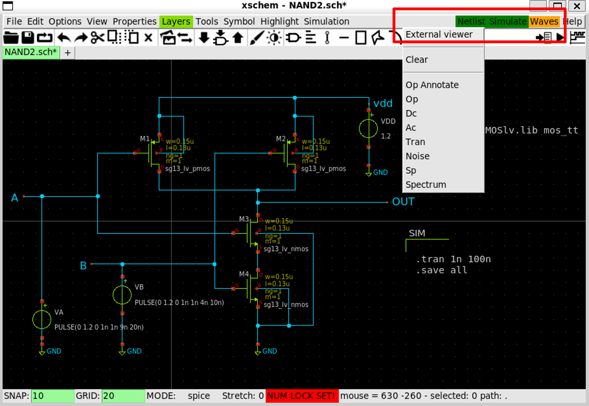
- Click on
Wavesbutton and selectExternal viewer
- In
GAW GUIopened, click on a panel first, then click on the signal you want to display