4.2 Implementation with LibreLane
0. Prerequisite
It is assumed that you already install the opensource design tools using docker.
1. Run the UNIC-CASS Docker image
- Open a terminal and change the directory to the uniccass-design-tools as s described in (Installing design tools using docker)(/training/2.2-AMS-docker-remote.html), and run
make start:
cd $HOME/projects/uniccass-design-tools
make start
2. Writing the Verilog files
We first need to write some verilog files: a digital circuit and its testbench.
Below is the same code you will see in the IVerilog & GTKWave tutorial page.
Create the counter.v and counter_tb.v by running the following command in the uniccas-design-tools docker shell:
module counter(
    input clk, nrst,
    output reg [3:0] ctr_out
);

reg [3:0] ctr;

always@(posedge clk) begin
    if (!nrst)
        ctr <= 0;
    else
        ctr <= ctr + 4'b1;
end

always@(*)
    ctr_out <= ctr;

endmodule
module counter_tb;

reg nrst,clk;
wire [3:0] c;

counter UUT(.ctr_out(c),.clk(clk),.nrst(nrst));

always begin
    #10
    clk = ~clk;
    $display("Counter value:%b @ time %f",c,$time);
end

initial begin
$dumpfile("test.vcd");
$dumpvars(0,counter_tb);

// we have to start somewhere
clk = 0;
nrst = 0;

#15
nrst = 1;

#100

$finish;
end

endmodule
3. Create config.yaml file for the counter design
To implement the design in LibreLane, we have to create a configuration file (often called config.yaml) to tell LibreLane what is the design/entity/module name (DESIGN_NAME), verilog source files (VERILOG_FILES), clock signal (CLOCK_PORT) and the clock period (CLOCK_PERIOD). These variables are the most essential variable for the flow. You can also set other variable in the flow.
DESIGN_NAME: counter
VERILOG_FILES: dir::counter.v
CLOCK_PORT: clk
CLOCK_PERIOD: 10 # 10ns = 100MHz
4. Run the implementation flow
librelane --pdk ihp-sg13g2 config.yaml
If the flow runs successfully, you should see that all the checks are passed. Otherwise, you will have to debug to see what is wrong.
* Antenna
Passed ✅

* LVS
Passed ✅

* DRC
Passed ✅

[07:29:29] INFO     Saving views to '/home/designer/shared/runs/RUN_2025-12-04_07-28-30/final'…             state.py:209
[07:29:29] INFO     Flow complete.
The results are stored in runs directory. You can find the Openroad database for each step in this directory and also the GDSII file.
5. View Your Design in Openroad
To view the results in Openroad, run the following command:
librelane --pdk ihp-sg13g2 config.yaml --last-run --flow OpenInOpenROAD

It is a good way to view and/or debug the design using the Openroad GUI because Openroad is used for the backend flow.
For example, to view the clock tree, click on Windows » Clock Tree Viewer. In the clock tree viewer tab on the right pannel, click on Update button.
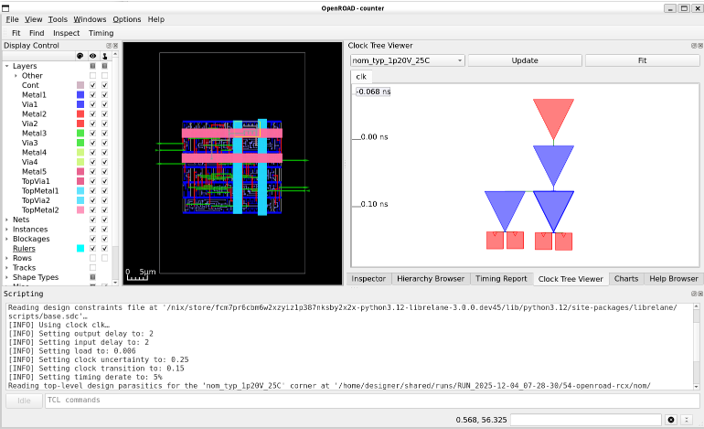
You can also view the timing report by selecting Timing report tab, then click on Update button.

6. View the GDSII file in Klayout
To view the results in Openroad, run the following command:
librelane --pdk ihp-sg13g2 config.yaml --last-run --flow OpenInKLayout
This is the default view of the output GDSII in Klayout.
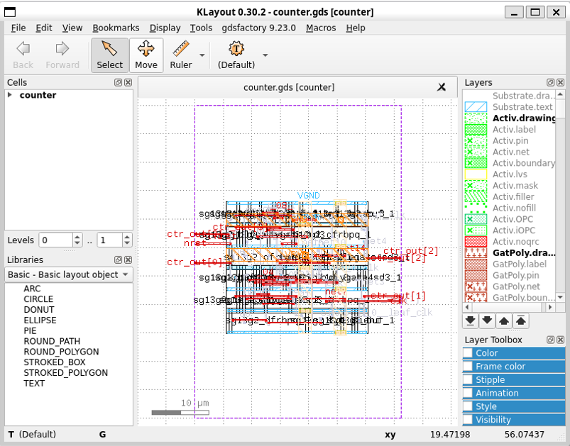
With some customizations such as right-clicking on the layer pannel and selecting Hide Empty Layers, clicking on View and deselect Show Texts, and clicking on Display and selecting Full Hierarchy, you can see the layout of the design with all the used layers as follows.

what’s next
You can learn more on how to use the LibreLane using the tutorial in Heichip workshop 2025